![]() Where to find the new
feature
Where to find the new
feature
![]() Helpful hints
Helpful hints
Compatibility With Previous Versions
DataCAD 22 contains a collection of new features and enhancements designed to increase your productivity.
The DataCAD 22 drawing file format is currently compatible with DataCAD 15 through 21. However, you must
use the "Save As" command in the "File" menu to save files backward to older version
formats.

Figure 22.1: File, Save As, Type
SketchUp 2017 through 2019 support
In addition to the existing support for SketchUp 7, 8, and 2013 through 2015 files, DataCAD's
translators have been updated to support reading and writing SketchUp 2016 through 2019 formats.

Figure 22.2: File, Export, SketchUp Dialog
Insert PDF as Image
A new option, PDF, has been added to the Insert pull-down menu. By default, the pages of the PDF file you select will automatically be converted to 300 dpi bitmaps in PNG format, and located in the same folder as the original(s).
Dynamically or Fixed Size Placement
There are two methods you can use to place a PDF bitmap in your drawing: Dynamically Sized and Fixed Size. For Dynamically Sized, you will be prompted to draw a rectangle for each page in the document. For Fixed Size, you will be presented with a pre-scaled bounding box based on the PDF's paper size and the current plot scale.

Figure 22.3: PDF to Image Settings
You can control the image type and resolution of the PDF pages you convert. If the source documents change, you can reconvert individual pages or use the Insert > PDF to Image Management > Reconvert All option to reconvert all the PDF pages that you have inserted in your drawing.
PDF Tools
Two PDF Tools have been added to the File pull-down menu: PDF Merge and PDF Security.
PDF Merge
Use PDF Merge to combine several PDF files into a single document. At first, you are
prompted to enter the name of the master document that will contain the merged files. The second step is to
select the PDF files to merge. In the file dialog, multi-select the files to merge then click
Open.
Note: The merge function does not allow combining password-protected files. Prior to
attempting the merge, the files you select are checked for passwords and the process will be cancelled if
any of them require one.
PDF Security
Use the PDF Security options to set document restrictions or to password protect existing
PDF files.

Figure 22.4: PDF Restrictions Dialog
PDF Password Protect
To apply a password to one or more documents, select File > PDF
Security > Password Protect. In the file dialog, select the PDF file(s) you
would like to create a password for then click Open. In the Password dialog, enter the
password to apply and click OK. Files that are already password-protected will be skipped.
Restrictions
To set restrictions, select File > PDF Security >
Restrictions. In the file dialog, select the PDF file(s) you would like to apply
restrictions to then click Open. In the PDF Restrictions dialog, check the document
restrictions to apply.
The PDF Restrictions dialog options conform with Adobe Acrobat's permission options. The items you
check will be restricted (not allowed) by Acrobat, and third-party viewers that adhere to these
standards.
Printing
Check Printing to prevent the document from being printed.
High Resolution
Check High Resolution to restrict printed output to 150 dots per inch.
Content Copying
Check Content Copying to prevent the document's contents from being copied.
Content Accessibility
Check Content Accessibility (not recommended) to prevent text access for screen reader devices for the
visually impaired.
Changing the Document
Check Changing the Document to prevent changes to the document's contents.
Commenting
Check Commenting to prevent adding annotation to the document.
Form Filling
Check Form Filling to prevent form field fill-in or signing.
Document Assembly
Check Document Assembly to prevent combining or attachment with other documents.
Page Extraction
Note: Page Extraction is the minimum restriction for password-protected documents and
cannot be unchecked.
PDF Watermark
Use PDF Watermark to overlay a custom bitmap on each page of PDF file(s) you select. The bitmap you select
will be made 50% transparent and will fit into a square, expanded to the extents of the page width.
To add a watermark to each page of a PDF document, select File > PDF
Watermark. In the File dialog, select the PDF file you would like to watermark then click
Open. In the Select Image dialog, select a bitmap to use as a watermark then click
Open.
Object Viewer Enhancements

Figure 22.5: DataCAD's Object Viewer Application
Several features and components have been added to DataCAD's Object Viewer to make working with a rendered view of your model more interactive.
Standard Toolbar

Figure 22.6: Object Viewer's Standard Toolbar
The Standard Toolbar contains icons for material selection, copying, pasting, and undo, redo, and reset.
When the selection icon is toggled on, navigation with the mouse is disabled. In selection mode, you can
click on any surface of your model to make the corresponding material active for editing. You can then use
the Material Properties and Material Color toolbars to customize the selected material.
Note: You can toggle selection mode on and off using the [S] hotkey.
You can copy the properties of one material and apply it to another by using the Copy Material and Paste
Material icons. These functions are also available from the Edit pull-down menu, the Material Toolbar's
context menu, or by using the standard [Ctrl] + [C] and [Ctrl] + [V] shortcuts.
After making changes to a single material, you can use the Undo, Redo, and Reset icons to move backward and
forward through the changes or reset the material to its original properties.
Material Toolbar

Figure 22.7: Object Viewer's Material Toolbar
In the Material Toolbar, you can browse the material properties associated with the various objects within
your model. The four icons along the top of this toolbar toggle what appears in the list. From left to
right, the icons correspond to: Current Model's Materials, Available Material Definitions, Available
Bitmap Textures, and Color Palettes.
The list of your model's materials appears in the order they were generated when your DataCAD drawing
was converted to o2c format. So, it is important for you to know this list will change when you add new
entities and materials or change which layers in your drawing are on and off.
Current Model's Materials
Each material has a corresponding index number. However, you can also add a name to each material, so they
are more-easily identified.

Figure 22.8: Materials Toolbar - Current Project's Materials
Copying and Pasting Material Properties
You can take all the properties (except the source image name) from one material and apply it to another by
using the copy and paste functions available in the Material Toolbar.
Available Material Definitions
In the Material Browser, clicking on the first folder icon displays a list of pre-defined materials from
DataCAD's material library. Notice that two new folder icons appear. The first icon allows you to set
the path for browsing pre-defined materials. The second toggles the display of materials in
sub-folders.

Figure 22.9: Materials Toolbar - Available Materials Browser
Available Bitmap Textures
In the Material Browser, clicking on the second folder icon displays a list of bitmaps from DataCAD's
texture library. Just as with pre-defined materials, two new folder icons appear.

Figure 22.10: Materials Toolbar - Available Textures Browser
Color Palettes
You can use the Material Browser's color palette to change the diffuse or reflection color of the
currently selected material.

Figure 22.11: Materials Toolbar - Color Palettes
Views & Schemes Toolbar
Use the Views & Schemes Toolbar for quick access to the views and material schemes you have saved for the
current model. Clicking on a view name will immediately change the viewing position in the Object Viewer.
Clicking on a scheme name will immediately change the material scheme of the entire model. Select the
'' scheme to restore the original materials and textures.
Working with Schemes
The changes you make to the materials and textures in your project can be saved and recalled by name using
Schemes. This allows you to explore and present multiple scenarios for interior and exterior finishes in
the same model.
When you first start the Object Viewer, the only thing that appears in the Schemes portion of the Views &
Schemes Toolbar is . You can click anytime to restore your project to its original state. The schemes you
add to your project appear in the Schemes section of the Views & Schemes Toolbar.
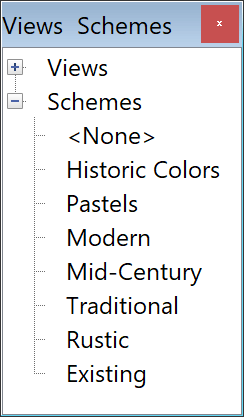
Figure 22.12: The original state of your design can be restored when you click
<None> in the Views & Schemes Toolbar
Locking and Unlocking a Scheme
You can lock a scheme to prevent making alterations.
Edit Material Toolbar

Figure 22.13: Object Viewer's Edit Material Toolbar
Use the Edit Material Toolbar to fine-tune the selected material's properties and its rendered display.
There are five slider bars that let you control how the material's surface is affected by light.
For entities that had materials assigned to them with Apply Texture enabled, there will be additional
options available.
Note: Certain material properties can only be set in DataCAD prior to launching the Object
Viewer via the Edit Materials Dialog.
These are Smoothing, Apply Texture, and Texture Scale.
• Ambient Increase this value to simulate plastic
• Diffuse Decrease this value to simulate velvet
• Reflection Increase this value to simulate glossy surfaces like chrome
• Opacity Increase this value to simulate transparent materials like glass
• Refraction Less than 10 simulates water; 10 equals air (no refraction); more than
10 simulates glass
Render Reflections
By default, all materials can reflect light from the surrounding environment. How much of that light is
reflected is determined by the reflection value. A material's reflective property can be disabled
entirely by unchecking Render Reflections. It's a good practice to only enable reflections on surfaces
like a mirror, polished metal, or glass since additional calculations have to be made during raytracing for
each 'reflective' polygon in your model.
Self-Illuminate
Use the Self-Illuminate option on surfaces that should always appear as bright as possible. When
Self-Illuminate is checked, the corresponding material will not be affected by other lighting conditions in
the scene.
Render Backface
If surfaces appear to be missing from your model, you can check Render Backface to force the Object Viewer
to render both sides of the material's corresponding polygons. Only check this option when necessary
since it will increase the time required to render your model.
Change Texture
You can change the image source of any material that has a bitmap texture assigned.
Render Black Pixels Transparently
You can set black (RGB, 0, 0, 0) pixels in the texture's image to render transparently.

Figure 22.15: Image of person on bicycle on black background

Figure 22.16: Image of person on bicycle with black pixels rendered transparently
Mix Texture with Rendered Color
You can tint the bitmap texture with the material's rendered color.

Figure 22.17: Grey shingle texture tinted green by mixing with material's diffuse
color
Apply Texture as Reflection Map
You can set the texture so it is applied as a reflection on the material's surface.

Figure 22.18: Brushed stainless faucet rendered with reflected stainless texture
Apply to All
The Apply to All toggle at the bottom of the Edit Material toolbar is a powerful option that should only be
used in special cases when you want to make changes to all of the materials in your project at once. When
Apply to All is toggled on, any change you make to an individual material setting will be applied to all
materials. So, if you increase the ambient value of the currently selected material, all the other
materials will inherit this value.
Edit Color Toolbar

Figure 22.19 Object Viewer's Edit Color Toolbar
You can control the diffuse and reflection colors of the selected material by clicking on the RGB Color
Cube, using the Brightness slider, or entering new values in the Red, Green, and Blue value editors. A
preview of the new color, surrounded by the old color, is shown to the left of the RGB value editors. One
is for the diffuse color and the other is for the reflection color.
Note: You can Right-click and Drag over the Color Cube to spin its orientation to reveal
all eight corners which correspond to Red, Green, Blue, Cyan, Magenta, Yellow, White, and Black.
Speed Hotkeys for Navigation Toolbars

Figure 22.20: Object Viewer's Pan, Rotate, and Walkthrough Toolbars
Prior to Clicking and Holding on any of the navigation icons (Pan, Rotate, and Walkthrough) for continuous
movement, you can press either or both of the [Ctrl] and [Shift] keys to adjust the speed.
• Click & Hold for Normal Speed
• [Ctrl] + Click & Hold for Half Speed
• [Shift] + Click & Hold for Double Speed
• [Ctrl] + [Shift] + Click & Hold for 5x Speed
View Stats Toolbars
The View Stats toolbars are now updated dynamically while you navigate using the mouse.

Figure 22.21: Object Viewer's View Stats Toolbars
View Manager

Figure 22.22: Object Viewer's View Manager Dialog
You can manage your saved views and associate them with specific schemes and backgrounds with the View
Manager.
Slideshow
Displays each of your saved views in sequence, one second at a time.
Save Screen
Use the Save Screen option to save the current view to a bitmap on your hard disk in either, BMP, EPS, GIF,
JPG, PCX, PNG, TGA, or TIF formats. The output resolution of the image will match the current size of the
Object Viewer window. Unlike Save Image, Save Screen is not limited to an output width of 2048 pixels.
Save Image
Save Image has been enhanced so you can now render to EPS, GIF, JPG, PCX, PNG, TGA, and TIF formats.
Previously, BMP was the only supported image format.

Figure 22.24: Object Viewer's Save Image Dialog

Figure 22.25: Object Viewer's Save Image As Dialog
Full Screen Mode
Full Screen Mode displays the current view using the whole screen and hides the application title bar,
menus, and all the toolbars that are currently displayed. Use the F11 hotkey to toggle Full Screen Mode on
and off.
Batch Rendering
You can render multiple views all-at-once. Since this may take a lot of time (depending on the number of
views you select, their complexity, the output resolution, and your computer's processing speed), you
can schedule this to occur during a break or after hours.

Figure 22.26: Object Viewer's Batch Rendering Dialog
Material / Texture Filters & Effects

Figure 22.27: Various Filters and Effects Applied to DataCAD Model
You can use Filters & Effects to alter or enhance material properties and bitmap textures. You can use
filters and effects such as Sepia and Newsprint for abstract presentation or make lighting adjustments by
applying Bright for better clarity.
In all, there are more than 35 filters and effects that can be applied to all materials at once, or one at
a time.
None
Select the 'None' filter to restore the material and texture properties to their original
values.
Artistic
Bump
Applies a waffle iron effect on textures. Set the Bump Factor to adjust the size.
Checkerboard
Replaces textures with a black and white checkerboard. Set the size of the squares in pixels.
Edges
Highlights edges in textures by intensifying outlines of high contrast areas and darkening areas of low
contrast. You can set sensitivity of edge detection by value.
Engrave
Applies a woodcut effect to textures by removing the color and generalizing areas of the image into high
and low tones. Set the factor from 1 (thin) to 10 (thick).
Grid
Applies a grid effect to textures by adding a white border around the image. Set the width of the gridlines
in pixels.
Metal
Creates a metallic effect by applying all textures as reflection maps.
Newsprint
Applies a halftone pattern to textures to simulate a continuous tone with dots.
Spray Paint
Applies a spray paint effect to textures by randomly choosing colors from the image. You can adjust the
spray from 1 (fine) to 100 (coarse).
Note: You can use the Seamless filter to remove the hard edges created by the Spray Paint
filter.
Threshold
Transforms the RGB values of pixels in textures that fall above the threshold you set to 255 and values
that fall below to 0.
Transparent
Sets the Opacity of all materials to 10% (90% transparent).
Color
Bleed
Intensifies the color of textures by expanding the image's color palette.
Fewer Colors
Reduces the color palette of textures down to 16 colors and dithers the resulting image.
Huey
Changes the hue, saturation, and brightness of textures to create an artistic effect.
Invert
Creates a negative image of material colors and textures by reversing the color values.
Mix
Changes the color of materials and textures by mixing the color you select with the diffuse, reflective,
and image colors.
Detail
Blurry
Softens textures by smoothing transitions between hard edges and shaded areas.
Despeckle
Removes noise from textures by filling in pixels that would otherwise appear as dots. The fill color is
determined by the color of the surrounding pixels.
Noisy
Adds noise to textures by modifying the intensity of RGB values in randomly selected pixels.
Sharp
Sharpens the detail of textures by increasing the contrast around edges in the image.
Distort
Mirror
Reverses the horizontal orientation of textures.
Motion
Blurs textures in a horizontal direction to simulate movement. This is analogous to taking a picture of a
moving object with a slow shutter speed.
Wavy
Applies a radial ripple effect to textures.
Lighting
Auto-Contrast
Improves the image contrast of textures by making dark pixels blacker and light pixels whiter.
Bright
Brightens the entire model by pushing the material's Ambient and Diffuse properties to 80%.
Dark
Darkens the entire model by pushing the material's Ambient and Diffuse properties to 30%.
Enhance
Automatically adjusts the RGB values of pixels among areas of different colors and shades.
Gamma
Brightens the midtones of textures without dramatically altering the shadows and highlights.
Lit
Removes all shading from materials by enabling the Self-illuminate property.
Painting
Mosaic
Applies a stained-glass effect to textures.
Oil Paint
Applies an oil paint effect to textures. Use a lower value to preserve more detail and a higher value to
exaggerate the effect.
Note: Using higher values will increase the time it takes to apply the effect.
Watercolor
Applies a watercolor effect to textures by 'smearing' the pixels of the image.
Retro
Greyscale
Converts the material and texture colors to monochrome shades of grey.
RGB: 29.9%, 58.7%, 11.4%
Sepia
Converts the material and texture colors to monochrome shades of sepia.
RGB: 112, 66, 20
Text
Text
Adds a text string you enter in the font you select to the center of the texture's image.
Special
Seamless
Removes the seam between tiles by quartering the image and duplicating the quadrants in opposite corners of
the image.
Edit Texture
Highlight Edit Texture in the Material Toolbar's context menu to access options to change the
orientation of a bitmap texture.
Rotate 90 (Clockwise)
Rotates the image 90 degrees clockwise.
Rotate 90 (Counterclockwise)
Rotates the image 90 degrees counterclockwise.
Rotate 180
Rotates the image 180 degrees.
Mirror
Reverses the horizontal orientation of the image.
Flip
Reverses the vertical orientation of the image.
Quick o2c

Figure 22.28: Quick o2c
With all of the features that have been added to the Object Viewer, some of you have requested an option to display a 'plain' o2c window when you want to just get a 'quick' view of your model, and don't require all of the other interactive features.
To display a 'Quick' o2c Player, hold down the [Ctrl] key while launching the Object Viewer from a toolbar icon or menu and DataCAD will show your model in a stripped-down o2c window. This window is modeless and will remain open while you continue to work in DataCAD. You can also launch multiple Quick o2c windows based on different views of your model. Quick o2c windows that are still open when you exit DataCAD will be closed automatically, and their size and position is not remembered.
Note: Extended character code #3049 has been added so you can launch Quick o2c from a custom toolbar icon.
Eye Dropper

Figure 22.29: DataCAD's Eye Dropper with magnified box enabled
An Eye Dropper icon has been added to DataCAD's Color Picker dialog and the Edit Color toolbar in the Object Viewer. Whenever you want to set the current color based on a pixel anywhere on your desktop, click the Eye Dropper icon, then move the cursor over the point on your desktop you'd like to match, then click to 'grab' the color.
Note: You can use the [Ctrl] key to toggle between the color preview and a magnified box surrounded by the current color.
RoofIt Macro Enhancements
Two new options, Set Colors and Set Layers have been added to the RoofIt macro's Settings menu. This allows you to specify the colors and layers for the various roof components. Previously, everything was modeled in the current color and on the current layer.
Set Colors Menu
Roof Color (Red by default)
Attic Color (Yellow by default)
Rake Color (Cyan by default)
Fascia Color (Lt Grey by default)
Soffit Color (Brown by default)
Gable Color (Green by default)
Gable In Clr (Lt Magenta by default)
Note: Previously, the Gable Color was set by toggling On EndWall which has been renamed to
Gable Walls.
Set Layers Menu
Roof Layer (RF Roof by default)
Attic Layer (RF Attic by default)
Rake Layer (RF Rake by default)
Fascia Layer (RF Fascia by default)
Soffit Layer (RF Soffit by default)
Gable Layer (RF Gable by default)

Figure 22.30: RoofIt Macro Enhancements
Drawing Window Opacity

Figure 22.31: Transparent Drawing Window
A new option, Drawing Window Opacity has been added to the Drawing Context Menu. To access this feature,
[Ctrl] + Right-click on a blank area of your drawing (i.e., not over an entity), and select Drawing Window
Opacity. A dialog appears where you can enter a value from 10 to 100 to set the drawing window's
opacity. Values less than 100 will cause other drawing windows to 'show through' when the
transparent window is on top. This setting is remembered on a per-drawing basis and can be used to compare
two drawings by placing one over the other.
In the example above, the 'newer' drawing is 'above' the 'older' drawing. The newer
drawing's opacity is 66% and the older drawing's opacity is 100%. The newer drawing will appear
'brighter' than the older drawing when its opacity is greater than 50%.
Note: Windows' MDI (Multiple-document Interface) only allows one drawing window at a
time to be maximized within DataCAD's program window. So, it is easier to compare two drawings when
they are in their restored (non-maximized state).
Mixed-Mode DPI Awareness
DataCAD automatically sets the scaling factor and font height for dialogs and toolbars based on their corresponding monitor's display scaling percentage. Previously, DataCAD would only adapt the program interface for whichever display was designated by Windows as the Primary (a.k.a. Main). Now when you drag dialogs from one monitor to another, DataCAD will rescale them if necessary so they display consistently.

Figure 22.32: DataCAD's About Dialog shown at several scaling factors
DataCAD automatically sets the scaling factor and font height for dialogs and toolbars based on their
corresponding monitor's display scaling percentage. Previously, DataCAD would only adapt the program
interface for whichever display was designated by Windows as the Primary (a.k.a. Main). Now when you drag
dialogs from one monitor to another, DataCAD will rescale them if necessary so they display
consistently.
If, in addition, you would like dialogs and their interface text to appear even larger, you can apply an
enlargement beyond the default size.

Figure 22.33: Dialog Box Enlargement Slider
In Program Preferences, on the Interface Tab, you can use the Dialog Box Size slider to make dialogs appear
larger.
In addition, you can customize the font that is used in dialogs by modifying the [Dialogs] section of
DCADWIN.ini.
Productivity Enhancements
Symbol Browser Show Nested
A new option, Show Nested, has been added to the Symbol Browser's
Options menu. This is a per-folder setting. When enabled, only the top level of
'parent' symbols will be shown in the Symbol Browser. This option is especially useful when
browsing Drawing symbols that contain many nested elements.
Mask Selection in Geometry Offset
The Mask selection option is now available in the Geometry,
Offset menu. Use the Mask option to set which entity types and related
properties should be included for the offset entity selection.
Fat Cursor
A new option, Fat Cursor, has been added to the 2D Settings menu. Toggle this option On to
set the weight of the drawing cursor larger than the default of 1; the maximum value is 9. Setting the
weight of the cursor to a value of 3 can be helpful when drawing over bitmaps and fills that otherwise make
the cursor hard to see.

Figure 22.34: Fat Cursor shown over satellite image
Change Pitch, Angle, or Grade of Flat Polygons and Slabs
You can now change the pitch of 'flat' polygons and slabs (parallel to the ground plane) via 3D
Edit, Polygons / Slabs and the Entity Properties Editor.
Symbol Explode Include Off Layers
A new option, Include Off Layers, has been added to the Symbol Explode menu. This option is available when
Symbol Layer Control is set to either Per Definition or Per Instance. When using Per Instance Layer Control
and exploding symbol instances that include nested symbols, the on/off layer settings are transferred to
the unexploded, nested symbols.
Sun Shader & Symbol Layer Control
The Sun Shader now recognizes on/off state of layers when Symbol Layer Control is set to either Per
Definition or Per-Instance.
Custom Elevation: Bisect
A Bisect option has been added to the New/Custom Elevation menu to make it easier to define an Elevation
View along the bisector of the angle between two lines or walls.
XREF: Show Hatch / Show Fill
Two new options, Show Hatch and Show Fill have been added to the XREF Entity, XREF Tools context menu.
Uncheck either of these options to suppress the display of hatches and fills on a per-XREF basis. These
settings do not apply to Smart Wall hatches and fills.
Multi-Scale Plotting Layout Divisions
The maximum number of multi-scale plotting layout divisions has been increased from 99 to 999.
Symbol Insertion Point by Center
A new option, By Center, has been added to the Save Symbol routine. This option appears when you are
prompted to click an insertion point for the symbol. Picking this option will cause the symbol's
insertion point to be located at the center of the selected entities' extents. This option is also
available when you redefine a symbol.
Miscellaneous Enhancements
1. A new option, Text Cursor, has been added to the Utility -->
Settings menu. If toggled on (the default), DataCAD will display a Carat (i.e. Text
Cursor) when you are entering text. If toggled off, the standard drawing cursor will be displayed instead.
When entering either PText or MText, this toggle is also displayed in the menu at S8. This setting is
remembered on a per-drawing basis.
2. The Color Palette dialog is now resizable.
3. The DXF/DWG Color Mapping dialog is now resizable.
4. Setting the background color in the Object Viewer now displays the DataCAD Color Palette and Custom
option for the Color Picker w/ Eye Dropper instead of the Windows standard Color Picker.
5. Added support for DMX macros when using 'M' action code in toolbars. The string for M= in the
DTB file can be MyMacro, MyMacro.dcx, or MyMacro.dmx. A popup message will appear when the macro specified
cannot be found.
6. Dialog-related hotkeys:
[Shift] Restore dialog to default size and center position
Pressing and holding the [Shift] key when invoking and displaying a form will reset the dialog to its
default size and position.
Pressing and holding the [Shift] key when launching DataCAD will reset the application window to its
default size and position.
[Ctrl] + [Shift] Restore dialog to center using previous size
Pressing and holding the [Ctrl] & [Shift] keys when invoking and displaying a form will restore and center
the dialog over DataCAD's application window, or the form that is currently open.
Note: Pressing and holding the [Ctrl] & [Shift] keys when launching any Windows program
will cause the application to run as administrator.
New Configuration Settings
DataCAD 22 contains new configuration settings which you can customize to override the default behavior
of new and existing features to better suit your personal workflow. Unless noted otherwise, the
following INI keys correspond to values that are not directly accessible in Program Preferences or
DataCAD's interface. Before making changes, close all drawings and exit DataCAD, then open
DCADWIN.ini file using a text editor such as Notepad. DCADWIN.in is in the DataCAD 22 installation
folder (C:\DataCAD 22\DCADWIN.ini by default).
Note: Prior to making any changes, you should make a backup copy of DCADWIN.ini in
case you need to return the program to its previous state.
Dialog Font
To customize the font that is used in dialogs, modify the FontName key in the [Dialogs] section of
DCADWIN.ini.
[Dialogs]
FontName=Segoe UI
Point_Size=9
Style=
The default dialog font is Segoe UI with a size of 9 points. If you would like text to appear larger,
you could change Point_Size=9 to Point_Size=11.
Note: This setting is independent of the dialog enlargement setting, so if you
increase the font size above the default value of 9, you'll need to set the dialog enlargement to
at least 125% (approx. 11 / 9) to accommodate the larger text.
Hint Font Size
You can now set the Hint Font Size in the [Hints] section of DCADWIN.ini. Previously, the size was
hard-coded to be 80% of the menu font size.
[Hints]
Point_Size=7
Delete to Recycle Bin
A new key, Delete to Recycle Bin, has been added to the [SymbolBrowser] section of DCADWIN.ini. Setting
this key to TRUE will cause DataCAD to send files to the Recycle Bin rather that deleting them.
[SymbolBrowser]
Delete to Recycle Bin=FALSE
Disallow No On Layers in Symbols
A new key, Disallow No On Layers in Symbols, has been added to the [General] section of DCADWIN.ini.
Setting this key to FALSE will allow symbols, with Per Instance Layer Control enabled, to have no On
Layers.
[General]
Disallow No On Layers in Symbols=TRUE
PDF Image Type / Resolution
New keys, Default Image Type, and Default Image Resolution have been added to the [PDF] section of
DCADWIN.ini.
[PDF]
Default Image Type=
Default Image Resolution=
The Default Image Type is PNG. Valid values are BMP, GIF, JPG, PNG, and TIF (not case-sensitive). The
Default Image Resolution is 300. Valid values are 72 to 1200 (dots per inch).
Note: If the resolution used to convert the image is not one of the predefined values
(100, 200, 300, 400, 500, or 600) then the menu item 'Custom: ' will appear followed by the
user-defined resolution. Otherwise, only the predefined values will be shown.
MaxChunkSize
A new key, MaxChunkSize, has been added to the [Bitmaps] section of DCADWIN.ini.
[Bitmaps]
MaxChunkSize=
The default value is 52428800 kb (50 MB). This value determines the largest portion (a.k.a.
'Chunk') of a bitmap to convert into metafile data for printing (and saving to PDF, WMF, and
EMF). 50MB should be large enough to process each bitmap in its entirety. The result should be one
metafile element per image. Previously, this value was a very tiny at 16 kb. So, PDF files that
contained bitmaps would end up with thousands of elements and the related 'bloat.' This change
should fix that.
o2c Fixed Material Keys
The MatFixed Flags key has been removed from the [o2cViewer] section of DCADWIN.ini. To force material
settings that were previously set with the MatFixed Flags key, the following keys should be used
instead:
[o2cViewer]
MatFixed Has Texture=
Set this key to TRUE so all material sub-objects can accept a texture in the Object Viewer.
Note: Except for bitmap textures that are applied as reflections, a material that has
a texture cannot have smooth edges.
MatFixed Texture Mask=
Set this key to TRUE so the color black (RGB 0,0,0) will render transparently in all materials.
MatFixed Self-Illuminate=
Set this key to TRUE so all materials render without shading.
MatFixed Texture Colorize=
Set this key to TRUE so all textures are colorized with the corresponding material's rendered
color.
MatFixed Render Backface=
Set this key to TRUE so all material sub-objects will be rendered on both sides.
MatFixed Texture Reflection=
Set this key to TRUE so all textures will render as reflections.
MatFixed Specular Reflection=
Set this key to TRUE so all materials can be rendered with reflections or FALSE, so no reflections are
rendered.
MatFixed Smooth Edges=
Set this key to TRUE so all tangent polygons within the same sub-object will be rendered as a smooth
surface (i.e. all the polygons that make up a sphere). By default, adjacent polygons with less than a
30-degree difference between their angles of orientation will be the same surface. This Edge Smoothing
value can be set in the Rendering Settings dialog.
Note: Except for bitmap textures that are applied as reflections, a material that has a texture cannot
have smooth edges.
MatFixed Texture Scale=
Set this key to a decimal value in meters so that all bitmap textures repeat with the same size
tiles.
MatFixed Texture Name=
Set this key to a fully-qualified path to a bitmap texture so that all material sub-objects will have
the same texture.
Object Viewer Min/Max Width/Height Keys
The following keys have been added to the [o2cViewer] section of DCADWIN.ini. Set these keys to
restrict the minimum and maximum size/proportion of the Object Viewer client area.
[o2cViewer]
o2c Max Width=
o2c Max Height=
o2c Min Width=
o2c Min Height=
Note: The 2048-pixel display width restriction has been removed from the o2c Client Area to accommodate 4K monitors.
Create Missing Folders
DataCAD will no longer create missing folders by default. To control this behavior, a new key, Create
Missing Folders, has been added to the [General] of DCADWIN.ini.
[General]
Create Missing Folders=FALSE
If FALSE, the default, DataCAD will look in the corresponding default path, or if that fails, the DataCAD Program Folder, when the previous path cannot be found. If TRUE, DataCAD will try to recreate the previous path.
Import Non-associative Hatch Dots
DataCAD will now import zero-length lines (endpoints of lines with matching coordinates) as
non-associative hatch dots. To control this behavior, a new key, Treat Zero-Length Lines As Dots, has
been added to the [DXF_DWG] section of DCADWIN.ini.
[DXF_DWG]
Treat Zero-Length Lines As Dots=TRUE
The default is TRUE. If FALSE, DataCAD will ignore zero-length lines during import.
Print Overshoots
The key, Print Overshoots, has been added to the [Printer] section of DCADWIN.ini. Set this key to TRUE
to always print overshoots, even if the attribute setting in the Utility, Display menu is toggled off.
Set this key to FALSE to never print overshoots. Set this key to DEFAULT to use the current display
setting.
[Printer]
Print Overshoots=DEFAULT
To Layer Color, Line Type, Line Spacing Toggles
The following keys have been added to the [General] section of DCADWIN.ini to control the Layer Color,
Line Type, and Line Spacing toggles in the Move To Layer and Copy To Layer menus:
[General]
Remember ToLayer Color=TRUE
Remember ToLayer Linetype=TRUE
Remember ToLayer Line Spacing=TRUE
For each of the above, the following values are used:
If TRUE, the associated menu toggle will always be On
If FALSE, the associated menu toggle will always be Off
If blank (or missing), the associated menu toggle will be remembered
Scroll Zoom to Cursor
A new key, Scroll Zoom to Cursor Position, has been added to the [General] section of DCADWIN.ini.
Setting this key to TRUE will cause DataCAD to zoom in and out toward the cursor's current position
rather than the endpoint of the rubber-band line. The default value is FALSE.
[General]
Scroll Zoom to Cursor Position=FALSE
Sort Paths In Preferences
A new key, Sort Paths In Preferences, has been added to the [General] section of DCADWIN.ini. The
default value is FALSE. Set this key to TRUE to have the list of program paths sorted alphabetically in
the Paths tab of Program Preferences.
[General]
Sort Paths In Preferences=FALSE
New Extended Character Codes
Extended character codes are used when programming icon toolbars and keyboard macros. When using any of
the following new extended character codes, you will use the syntax V= for a toolbar button which
executes just the one single command, A=10XX# in a toolbar button sequence that contains more than one
command, or 10XX# in a keyboard macro. For more information on toolbar programming, see the topic
“Creating Custom Toolbars†in Chapter 30 of the DataCAD Reference
Manual.
Material Files
3035 : Load a material file (INI)
3036 : Reload a material file (INI)
3037 : Assign a material to a color index (Load)
3038 : Assign a material to a color index (Reload)
Note: 3037 and 3038 apply to DataCAD's DMF (DataCAD Material File) when rendering
by color.
Toolbar Examples:
[Load Brick100]
Hint=Load Brick100
Icon=
A=^3035#^C:\DataCAD 22\Materials\Brick\Brick100$^
[Load Brick Materials]
Hint=Load Brick Materials (reload)
Icon=A=^3036#^C:\DataCAD 22\Materials\Brick\Brick100$^C:\DataCAD
22\Materials\Brick\Brick101$^C:\DataCAD 22\Materials\Brick\Brick200$^C:\DataCAD
22\Materials\Brick\Brick300$^C:\DataCAD 22\Materials\Brick\Brick301$^
[Color 42 to Brick100 (load)]
Hint=Change Material for Color 42 to Brick100 (load)
Icon=
A=^3037#^C:\DataCAD 22\materials\brick\brick100$^45$^
[Color 42 to Brick100 (reload)]
Hint=Change Material for Color 42 to Brick100 (reload)
Icon=
A=^3038#^C:\DataCAD 22\materials\brick\brick100$^45$^
PDF
3039 : Insert a dynamically sized PDF Image
3041 : Insert a fixed size PDF Image
3043 : PDF Settings
3045 : PDF Merge
3047 : PDF Password
3048 : PDF Permissions
Quick o2c
3049 : Launch Quick o2c
Enhancements to DCAL (DataCAD Applications Language)
DCAL for Delphi Enhancements
The following constants have been added:
maxpolyfence = 512; { Should not be less than maxpoly }
maxdiv = 128; { max Primary/Secondary divisions }
PathGUI = 73;
PathLayout = 74;
Note: Patho2cimporttexture = 48 has been removed.
The following functions have been added:
Attribute Functions:
Sys_Add_AtrStruct(aName : atrName; var struct; sz : byte) :
attrib;
Hdr_AddPut_AtrStruct(aName : atrName; var struct; sz : byte) : attrib;
Get_AtrStruct(frstatr : lgl_addr; aName : atrName; var struct; sz : byte) :
Boolean;
Miscellaneous Functions:
list_get(var list: list_type; addr: lgl_addr): boolean;
This function is used to get a list of layers from a GoTo View or MSP Detail.
For Example:
vaddr := pgsv.strtview;
while view_get(view, vaddr) do begin
vaddr := view.Next;
if view.flag1 = 0 then f_wrstr(fl, 'GoTo View:
')
else if view.flag1 = 1 then f_wrstr(fl, 'MSP Detail:
');
f_wrstr(fl, view.name); { Long Name }
addr := view.frstlyr;
f_wrstr(fl, 'Layers: ');
f_wrln(fl);
try
while list_get(list, addr) do begin
addr := list.next;
for i := low(list.Data) to high(list.Data)
do begin
if not isnil(list.Data[i])
then begin
getLongLayerName(list.Data[i], lname);
f_wrstr(fl, lname);
f_wrln(fl);
end;
end;
end;
except
on e: Exception do begin
f_wrstr(fl, 'DataCAD 21.02.00 or later required to get layer
list.');
f_wrln(fl);
end;
end;
end;
DCADPenToRGB(penNo: longint; var r: byte; var g: byte; var b: byte);
Use this function to convert a DataCAD pen number to an RGB triplet.
dwgpath(var str: str255);
Use this function to get the path of current drawing.
DataCAD_Version(): asInt;
This function returns the current DCADWIN.exe version as an integer.
Note: The drawing variable, PGSavevar.headerversion contains the version of
DCADWIN.exe at the time the current drawing was last saved.
The following sample macros have been added.
Spiral
Converted from DCAL for DOS
TooSmall
Converted from DCAL for DOS
Write_AEC
Converted from DCAL for DOS
The following sample macro has been updated.
atrBrowserForm
Now uses a single f_wrAtrStr function to extract Drawing, Entity, Symbol, GoTo View, MSP Detail, and
Symbol Text attribute strings.
undoStartTransaction();
undoEndTransaction();
These procedures mark the beginning and end of what the undo system sees as a
"transaction".
DCAL for C++ Enhancements
The following constants have been added:
#define maxpolyfence 512 /* Should not be less than maxpoly */
#define maxdiv 128 /* max Primary/Secondary divisions */
#define PathGUI 73
#define PathLayout 74
Note: Patho2cimporttexture 48 has been removed.
The following functions have been added:
list_get(list_type &list, lgl_addr &addr);
This function is used to get a list of layers from a GoTo View or MSP Detail.
DCADPenToRGB(longint penNo, byte &r, byte &g, byte
&b);
Use this function to convert a DataCAD pen number to an RGB triplet.
dwgpath(ShortString &str);
Use this function to get the path of current drawing.
undoStartTransaction();
undoEndTransaction();
These procedures mark the beginning and end of what the undo system sees as a
"transaction".
DCAL for DOS Enhancements
Note: The following functions were added to a previous version of DataCAD but were
never documented.
PROCEDURE UndoStartTransaction; BUILTIN 634;
PROCEDURE UndoEndTransaction; BUILTIN 635;
These procedures mark the beginning and end of what the undo system sees as a
"transaction".
For example, when creating a single line, the undo system sees the following:
• An entity was added
• It was drawn to the screen
• It was marked as the end of a "group"
These 3 steps are seen as a single "transaction" and will be "un-done" together.
PROCEDURE getLongLayerName(pLayer : lgl_addr; Name : IN OUT str80); BUILTIN 636;
pLayer is the address of the layer being queried
Name is the long name of that layer
FUNCTION Lyr_Find_LongName(Name : str80; pLayer : lgl_addr); BUILTIN 637;
Name is the layer name to look for
pLayer is the address of the layer if found
The function returns True if it found a layer by that Name
FUNCTION Get_InpStyl : integer; BUILTIN 638;
This function returns the index of the current input style where:
0 = Relative Polar
1 = Absolute Polar
2 = Relative Cartesian
3 = Absolute Cartesian
4 = Direction/Distance
PROCEDURE Set_InpStyl(InputStyle : integer); BUILTIN 639;
This function sets the index of the current input style where:
0 = Relative Polar
1 = Absolute Polar
2 = Relative Cartesian
3 = Absolute Cartesian
4 = Direction/Distance
PROCEDURE Get_DimFont(Ent : Entity; FontName : IN OUT str80); BUILTIN 640;
This procedure retrieves the name of the font used in the associative dimension, Ent
FUNCTION setMSPSheetToPlotByName(Name : str80) : boolean; BUILTIN 641;
Name is the name of the MSP sheet to make current
This function returns True if it was able to find a sheet with the Name provided
FUNCTION setMSPSheetToPlotByNum(SheetNum : integer); BUILTIN 642;
Makes SheetNum the current MSP sheet (1-256)
This function returns True if a valid SheetNum was passed in
FUNCTION GetMSPSheetName(SheetNum : integer; SheetName : IN OUT str80) : boolean; BUILTIN 643;
SheetName is the name of the MSP sheet specified by SheetNum
This function returns True if a valid SheetNum was passed in
PROCEDURE setToPlotQuickLayout(DoQuickLayout : boolean); BUILTIN 644;
DoQuickLayout tells DataCAD to default to plotting the Quick Layout rather than MSP
FUNCTION plotOpen10(PenWidth : integer; WinPaperSize : integer; PaperSizeX, PaperSizeY : integer; NumCopies : integer; PlotToFileName : str80; ErrorMessage : IN OUT str80) : boolean; BUILTIN 645;
PenWidth specifies the pen width in millimeters
WinPaperSize is the index into the available paper sizes
PaperSizeX / PaperSizeY specify the custom paper size in millimeters
NumCopies is the number of copies
PlotToFileName is the name of the plot file to create if plotting to file
ErrorMessage is a string to receive any error message (i.e. the printer doesn't support the paper
size specified in PaperSizeX / PaperSizeY
FUNCTION plotMode10(Mode : IN OUT mode_type; paperMin, paperMax, WindowMin, WindowMax, RotationCenter : point; RotationAngle : real; MaintainAspect : boolean; ErrorMessage : IN OUT str80) : boolean; BUILTIN 646;
Mode is what will be plotted
PaperMin and PaperMax specifies the custom paper size in millimeters
WindowMin and WindowMax specify the real-world coordinates of the viewport to be plotted
RotationCenter is the real-world coordinate of the center of rotation if the printer is setup to rotate
the print
MaintainAspect should be set to True if no distortion of the X or Y axis is desired
ErrorMessage is a string to receive any error message
This function returns True if no errors were encountered
PROCEDURE plotClose10; BUILTIN 647;
This procedure should be called after calling plotMode10
FUNCTION setPenTableNameToLoad(PenTableName : str80); BUILTIN 648;
PenTableName Name of Pen Table
This function returns True if successful
FUNCTION setPrinterByName(PrinterName : str80; ErrorMessage : IN OUT str80); BUILTIN 649;
PrinterName Name of printer
ErrorMessage is a string to receive any error message
This function returns True if successful
PROCEDURE GetPrinterNames(PrinterNamesArrary : IN OUT; TPrinterNamesArr; NumPrinters : IN OUT integer) BUILTIN 650;
PrinterNamesArrary will contain the names of the printers available to the system.
The type TPrinterNamesArr is declared as:
type
TPrinterNamesArr = ARRAY[1..50] of string[80];
NumPrinters is the number of printers found
PROCEDURE SetMacroHints(DoHints : boolean); BUILTIN 651;
DoHints tells DataCAD whether to display tooltips for the function key labels
Revision History
Thank you for printing this page. Please feel free to contact us for further assistance. You can call our sales department at +1 (800) 394-2231, Monday through Friday from 8:00 a.m. to 5:00 p.m. Eastern time or send an e-mail message to info@datacad.com.