DATACAD LLC
Software for Architects
www.datacad.com
P.O. Box 815
Simsbury, CT 06070
USA
Sales
(860) 217-0490 Main
(800) 394-2231 Sales
info@datacad.com
Technical Support
(860) 217-0567
help@datacad.com
Free DataCAD Forum
forum.datacad.com
Dear Valued Customer:
Thank you for your interest in DataCAD 23. As part of our dedication to continuous improvement and to
deliver the highest quality CADD products possible, this latest upgrade includes your most requested
enhancements. To get the most from DataCAD 23, please refer to the overview below. If you have any
questions about DataCAD 23, contact our technical support staff at help@datacad.com.
Thank you for supporting DATACAD,
![]()
Mark F. Madura
President/CEO
mark@datacad.com
![]() Where to find the new
feature
Where to find the new
feature
![]() Helpful hints
Helpful hints
Compatibility With Previous Versions
DataCAD 23 contains a collection of new features and enhancements designed to increase your productivity.
DataCAD 15 through 23 share the same drawing file format. However, you must use the Save As command in the File menu
to save files backward to older version formats (DataCAD 11 through 14).

Figure 23.1: File, Save As, Type
AutoCAD 2020 - 2023 Support
DataCAD 23 extends its compatibility with AutoCAD DXF and DWG files by adding support for R2020 - R2023 files;
enabling you to collaborate and share files with associates who use the latest versions of AutoCAD.
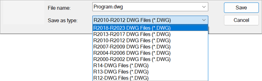
Figure 23.2: Export DWG Dialog
SketchUp 2020 - 2022 support
DataCAD 23 extends its compatibility with SketchUp SKP files by adding support for version 2020 through 2022 files;
enabling you to collaborate and share files with associates who use the latest version of SketchUp.
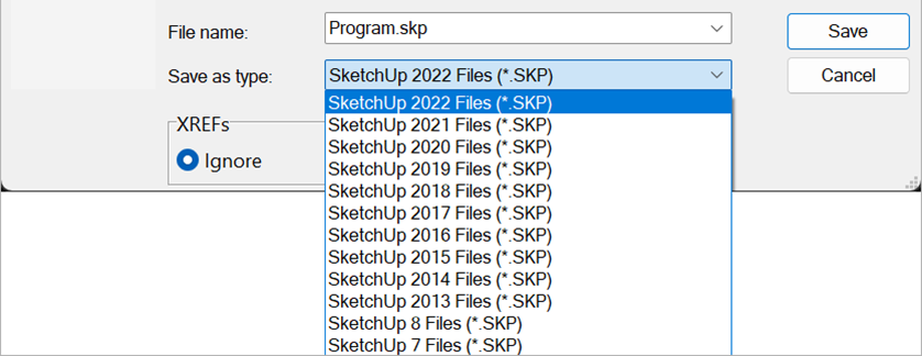
Figure 23.3: File, Export, SketchUp Dialog
Imaging Enhancements
In this major update, DataCAD's graphics pipeline has been enhanced to support greater versatility in construction and presentation documents. These improvements enable both the display and printing of fills and bitmaps with transparency, offering more control over the visual aspects of your designs. The new ability to incorporate 32-bit images into your drawings expands the range of your imaging options. Furthermore, we've introduced updated PDF Creation routines to support transparency and ensure smaller file sizes. With this progression in DataCAD's capabilities, we're confident you'll be able to refine the way you present and share your own designs.
Transparent Fills
There may have been times when you wanted to �ghost� a portion of your drawing or merge the colors of two overlapping filled areas to better illustrate your design intent. Previously, you were limited to using a solid color or completely knocking out an entire area. With transparencies, you can achieve a more subtle delineation.
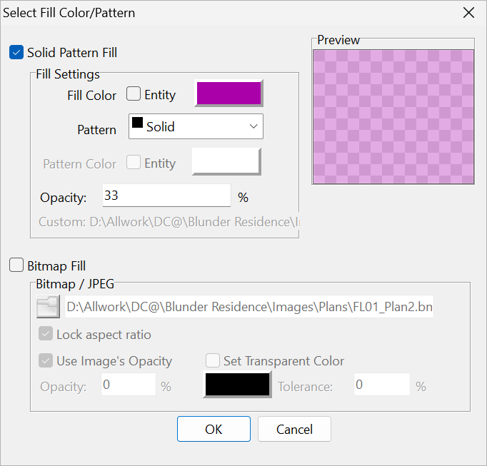
Figure 23.4: New SPB Fill Settings Dialog
In the Solid, Pattern, and Bitmap Fills (SPB-Fill) dialog, accessed via the Hatching menu, there�s a new input field to set the opacity. The default value is 100%, or completely opaque. You can set this value below 100 to create transparent fills. A setting of 50 will allow graphics behind the fill to �show through� and blend with the filled area.
32 Bit Bitmaps (Alpha Channel)
While there are several ways to use or apply transparency to Bitmap images you insert in your drawings, the most likely way is to
take advantage of image libraries that already have the background removed from objects such as people, cars, and trees.
Some formats such as PNG (Portable Network Graphics) allow each pixel to range from fully transparent to fully opaque. In the
SPB-Fill dialog, there is a new option in the Bitmap Fill section, Use Image�s Opacity. This option is checked by default which
means that DataCAD will display and print the image using its native transparent values if it contains any.
You can override the original image�s values by unchecking this option. This enables the field where you can set the opacity below 100%.
The value you enter here will apply to the entire image uniformly. Instead of this, you can check the Set Transparent Color option to
assign a specific color such as white or black to be transparent. Furthermore, you can set the tolerance from 0 to 100 to expand the
transparent areas to colors that are near the color you set.
New Image Formats
The latest version of DataCAD greatly extends the kinds of images you can incorporate into your projects. This provides expanded
compatibility with other software and gives you greater flexibility for where you can source your images. The following additional
image types are now supported.
- JPEG
JPE, JIF, JFIF - Windows Bitmap
DIB, RLE - TIFF
FAX, G3N, G3F, XIF - DICOM Medical Image
DICOM, DCM, DIC, V2 - Photoshop
PSD, PSB - JPEG2000
JP2 - JPEG2000 Code Stream
J2K, JPC, J2C - High Efficiency Image File
HEIC, HIEF, HEICS, AVCS, HEIFS, AVIF, AVIFS - WebP
WEBP - Microsoft HD Photo
WDP, HDP, JXR - Windows Icon
ICO - Windows Cursor
CUR - PaintBrush
PCX - Targa Image
TARGA, TGA, VDA, ICB, VST, PIX - Portable Pixmap
PXM, PPM, PGM, PBM - Wireless Bitmap
WBMP - Multipage PCX
DCX - DirectDraw Surface
DDS
This comprehensive range of supported formats ensures that you can work with varied image sources, regardless of their original format. So, whether you�re using cell phone pictures, graphics you�ve downloaded from the Internet, or even medical images, DataCAD has you covered.
New and Improved PDF Creation
Now that PDFs have become nearly ubiquitous and more common than other native formats such as DOC or DWG, we want to make sure DataCAD's PDF
tools are as comprehensive as possible.
Now when you print or batch print to PDF format, transparencies and 32-bit images are automatically handled, there's nothing further you need
to do to include them in the documents you give to your clients. In addition, you don't have to worry about using high-quality, high-resolution
images as they are also automatically compressed to keep file sizes to a minimum.
These advancements in PDF creation will not only increase the quality of your documents but also ensure your work is presented in the best way possible.
Batch Printing Enhancements
A major update to the batch printing interface provides features that automate the steps required to create PDF files from drawing layouts; Quick Layout, GoTo Views, and MSP Sheets. These include custom sorting, naming based on rules, and merging multiple documents into a single file.
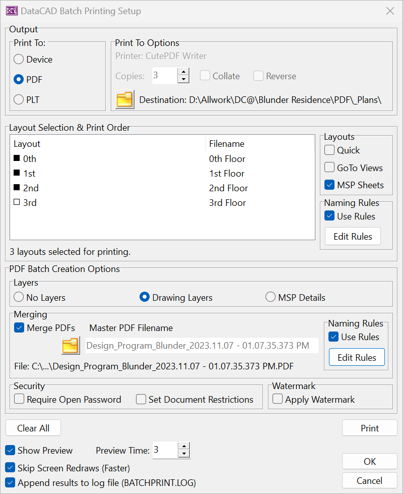
Figure 23.5: Enhanced Batch Print Dialog
Trim3D Macro
New 3D trimming routines, that will eventually be integrated directly into DataCAD, are now available in a new macro. These routines allow you
to find the intersection between 2D lines, 3D lines, and 3D Polygons and modify them accordingly to create custom shapes for roofs and other purposes.
The macro provides specific trimming methods which can be used in any view projection including plan, elevation, isometric, and perspective.
The behavior of these routines is like DataCAD�s cleanup commands where the result of the trim occurs on the �pick� side of the intersection point.
You can control whether to modify only the first, or both entities you select, or only display or add the intersection point(s) or line(s) to the
drawing. This allows you to study a particular condition without making changes to the model.
Main Menu Options
Line to Line
Trim 2D/3D Lines to 2D/3D Lines
Toggle On Line to Line if you want to trim one 2D/3D Line to another. If they intersect, the lines will be trimmed or extended, as necessary.
Line to Poly
Trim 2D/3D Lines to 3D Polygons
Toggle On Line to Poly to trim a 2D/3D Line to a 3D Polygon.
Poly to Poly
Trim 3D Polygons to 3D Polygons
Toggle On Poly to Poly to trim one 3D Polygon to another. Select the edge of the first polygon to modify, then select the edge of the second polygon to modify.
Edge to Edge
Trim 3D Polygon Edges to 3D Polygon Edges
Toggle On Edge to Edge to trim one polygon edge to its intersection with another polygon edge.
Edge to Poly
Trim 3D Polygon Edges to 3D Polygon Faces
Toggle On Edge to Poly to trim one polygon edge to its intersection with another polygon face.
Show Node #s
Display Index of Polygon Vertices
Toggle On Show Node #s to display temporary index numbers at polygon vertices.
Trimming Sub-Menu Options
Trim Ents
Modify Selected Entities
Toggle On Trim Ents to modify the entities. Toggle Off Trim Ents to leave the original entities as-is.
Trim to �
Modify First Entity
Toggle On Trim to � to only modify the first entity you select.
Trim Both
Modify Both Entities
Toggle On Trim Both to modify both entities you select.
Split
Split Entity At Intersection
Toggle On Split to �break� the line at the intersection point.
Split Both
Split Both Entities At Intersection
Toggled On Split Both to �break� both lines at the intersection point.
Show Points
Display 3D Intersection Points
Toggle On Show Points to display temporary point(s) at the intersection(s).
Show Lines
Display 3D Intersection Lines
Toggle On Show Lines to display temporary 3D Line(s) extending to the intersection(s).
Add Points
Add 3D Intersection Points
Toggle On Add Points to add point(s) at the intersection(s).
Add Lines
Add 3D Intersection Lines
Toggle On Add Lines to add 3D Line(s) extending to the intersection(s).
Add Helpline
Add Helpline Along Intersection of 3D Polygons
Toggle On Add Helpline to add an infinite line (parallel to the ground plane) along the intersection of two polygons.
Hatch Pattern Manager Advanced Options
The options provided in the Hatch Pattern Manager can be expanded beyond loading and purging patterns to include editing of various properties. To enable these advanced options, set the key, Advanced Options, to True in the HatchPatterns section of DCADWIN.ini.

Figure 23.6: Advanced Hatch Pattern Manager Dialog
External Hatch Patterns Context Menu
Right-click on an item in the external hatch patterns list to reveal the options; Rename, Change Scale, and Delete.
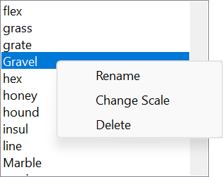
Figure 23.7: External Hatch Patterns Context Menu
� Select Rename to enable the edit field. The changes you make to the pattern name will be saved to disk when you exit the field.
� Select Change Scale to enter a new scaling factor for the pattern.
� Select Delete to remove the pattern from the hard drive.
Browse Folders
A Browse Folder icon allows you to change the path to look for hatch patterns from the default location of Support Files\Hatch Patterns\ to any location you require.
Save Changes Icon
The changes you make to the Display Scale drop-down, and Angle and Scale edit fields can be saved to disk by selecting the Save icon button.
Save As Icon
A Save As icon button allows you to save the currently selected pattern to a new name.
Hatch Pattern Edit Icon
A Hatch Pattern Edit icon button allows you to display the current hatch pattern definition in a string grid layout. This allows for direct editing of the Angle, X Offset, Y Offset, Delta X, Delta Y, and optional Pattern values.

Figure 23.8: Hatch Pattern Definition Editor
� Click Show/Refresh Preview to see the pattern displayed in a non-modal window.
� You can toggle the buttons in the Segment column to selectively enable/disable scanline definitions. If displayed, the preview is updated automatically when a segment is toggled on or off.
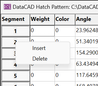
Figure 23.9: Hatch Pattern Editor Context Menu
A context menu provides options to Insert new or Delete existing segments.
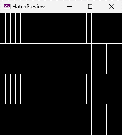
Figure 23.10: Hatch Pattern Editor Preview
Multi-View Window Enhancements
Magnetic Windows
It's now possible to 'magnetize' Multi-View Windows so they 'snap' to each other and the edges of your monitor(s).
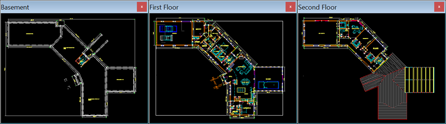
Figure 23.11: Magnetic Multi-View Windows
Customizable Dock Sites
You can now set which edge (Top, Bottom, Left, Right) of DataCAD's program window Multi-View Windows will dock to.
Docked Width & Height
You can now set the docked width and height of Multi-View Windows.
Minimum Width & Height
You can now set the minimum width and height of Multi-View Windows.
(See MultiView Windows in New Configuration Settings below)
Miscellaneous Enhancements
Drawing Information Dialog

Figure 23.12: Drawing Information Items
A new option, Drawing Version History, has been added to the Information Items section of the Drawing Information dialog. Check this option to display a list of versions and dates the current drawing has previously been saved in.
The state of the information item checkboxes in the Drawing Information Dialog is now remembered on a per-drawing basis. The default initial state of the checkboxes can be set in the Drawing Information Dialog section of DCADWIN.ini.
PDF Convert Multiple Pages Confirmation

Figure 23.13: Multi-page Convert Confirmation
A confirmation dialog will now appear before you insert multi-page PDFs. Select Yes to convert all pages, or No to convert the first page only.
64 Bit PDF to Image Conversion
A 64 Bit conversion library is now used by default to convert PDFs to bitmaps. You can revert to the 32-bit library by setting the key, Use 64 Bit PDF to Image Conversion, to False.
Drawing Repair
For convenience, the Repair option is now available from the File pull-down menu when a drawing is open. Selecting this option when one or more files are open will require you to close all files before continuing with the repair.
3D Entity Testing
The included angle between the beginning and ending angles of 3D Arcs, Cylinders, Cones, Truncated Cones, Spheres, Tori, and Surfaces of Revolution is now tested.
Larger Default Near Zero Tolerance
The previous default tolerance for near zero tests has been changed from 1E-12 (One Trillionth) to 1E-6 (One Millionth). So, if the length between two points is less than one millionth of a 32nd of an inch, it will be considered zero length.
User-definable Epsilon Values
The epsilon (i.e., near zero) values are now user-definable via DCADWIN.ini. The default is 1E-6 (One Millionth). The tolerance can be set independently for Angles, Length, Radius, and Text Size (See DCADWIN.ini in New Configurations Settings).
Error Codes
The entity error reporting routines have been updated to return codes that correspond to the invalid property. The following table is now included at the end of the error report.
Entity Error Code Reference:
----------------------------
100: Invalid Entity Type
101: Zero Length Line
102: Invalid Floating Point Value
103: Zero Length Radius
104: Zero Degree Angle
105: Invalid Number of Control Points
106: Invalid Number of Leader Control Points
107: Color Index Out Of Range
108: Invalid Number of Vertices
109: Invalid Point Array
110: Invalid Smart Entity Control Point Count
111: Invalid Smart Text Font Height
Note: Entities are marked as invalid based on the first test to fail. Entities that contain multiple errors will only report the first error discovered during the audit.
Batch Printing Bookmarks
A new key, Merged PDFs Add Bookmarks, has been added to the BatchPlot section of DCADWIN.ini. The default value is False. If True, DataCAD will use the Layout Filename to create a corresponding bookmark in merged PDFs.
DWF Background Color
Drawing files exported to DWF format now have a white background by default.
Identify, Set All
Identify, SetAll will now set the state of the SPB-Fill Boundary On/Off toggle.
o2c Textures
Any of the newly supported image file types can now be used as o2c textures.
Internationalization
The hard-coded messages that are used during program startup when a necessary file is not found have been expanded to include French, Portuguese, and Spanish strings. The OK button in this dialog now uses the local language string for OK.
'Filename' ' does not exist.' (English)
'Filename' ' no existe.' (Spanish)
'Filename' ' n''existe pas.' (French)
'Filename' ' n�o existe.' (Portuguese)
The hard-coded messages that are used to indicate DataCAD is unable to read message from message file have been expanded to include the following locations.
[BR] Brazil, [CZ] Czechia, [DE] Germany, [ES] Spain, [FR] France, [HU] Hungary, [IT] Italy, [LV] Latvia, [MX] Mexico, [PL] Poland, [PT] Portugal, and [RO] Romania.
BR: 'N�o � poss�vel ler a mensagem do arquivo de mensagem.'
CZ: 'Nelze prec�st zpr�vu ze souboru zpr�v.'
DE: 'Nachricht kann nicht aus Nachrichtendatei gelesen werden.'
ES: 'No se puede leer el mensaje del archivo de mensajes.'
FR: 'Impossible de lire le message � partir du fichier de messages.'
HU: 'Az �zenet nem olvashat� az �zenetf�jlb�l.'
IT: 'Impossibile leggere il messaggio dal file del messaggio.'
LV: 'Nevar nolasit zinojumu no zinojuma faila.'
MX: 'No se puede leer el mensaje del archivo de mensajes.'
PL: 'Nie mozna odczytac wiadomosci z pliku wiadomosci.'
PT: 'N�o � poss�vel ler a mensagem do arquivo de mensagem.'
RO: 'Nu se poate citi mesajul din fisierul cu mesaje.'
US: 'Unable to read message from message file.'
In Program Preferences, the defaults option in the Paths tab will now set the default paths based on the installed language.
For example:
The default path for Materials in English speaking countries is Materials\.
For French it should be Mat�riaux\
For Portuguese it should be Materiais\
For Spanish it should be Materiales\
New Configuration Settings
DataCAD 23 contains new configuration settings which you can customize to override the default behavior
of new and existing features to better suit your personal workflow. Unless noted otherwise, the
following INI keys correspond to values that are not directly accessible in Program Preferences or
DataCAD's interface. Before making changes, close all drawings and exit DataCAD, then open
DCADWIN.ini file using a text editor such as Notepad. DCADWIN.in is in the DataCAD 23 installation
folder (C:\DataCAD 23\DCADWIN.ini by default).
Note: Prior to making any changes, you should make a backup copy of DCADWIN.ini in
case you need to return the program to its previous state.
[General]
Require DCADWIN.ini on Startup
If True, the default, DataCAD will halt during program startup if DCADWIN.ini is not present.
If False, DataCAD will run using default values and DCAWIN.ini will be recreated.
Save All On Forced Shutdown
DataCAD's forced shutdown logic has been updated to be compliant with Windows 11 guidelines. If True, the default, all open drawings will be closed, then 'quick' saved (unused data such as deleted entities will not be purged). To cause all drawings to be closed but not saved during a forced shutdown, set this key to False.
Sort DCADWIN.ini On Exit
If True, the default, DCADWIN.ini will be sorted alpha numerically during program shutdown.
If False, sorting will not occur.
Sort GUI Files On Exit
If True, the default, DataCAD's GUI files will be sorted during program shutdown.
If False, sorting will not occur.
Use Internal Color Palette
If True, the default, DataCAD will read the embedded default color palette when the externally reference RGB file cannot be found.
If False, DataCAD will halt operation during startup when 'Default.rgb' cannot be found.
Use Internal Message Strings
If False, the default, DataCAD will halt during startup when any of the menu, message, and label files cannot be found. This includes DCADWIN.mnu, DCADWIN.lbl, DCADWIN3.lbl, DCADWIN.msg, and DCADWIN3.msg.
If True, DataCAD will only use the embedded files (the files on disk will be ignored).
Use Internal Support Files
If True, the default, DataCAD will read the embedded support files when the external files cannot be found. This includes DCADWIN.scl, DCADWIN.ang, DCADWIN.dis, and DCADWIN.dec.
If False, DataCAD will halt during startup when any of these are not found.
USER_LANG
Stores the language selected during installation (i.e., EN, FR, ES, PT).
Max Program Title Length
A hard-coded length of approx. 144 characters is applied by Windows to the application title when the Drawing Form is maximized, and its caption is concatenated onto DataCAD�s title bar. This can cause the drawing�s file name to get truncated or completely removed if it is in a deeply nested path. By default, if the fully qualified name is longer than 144 characters, the left-hand side of the string will be truncated and pre-pended with '...' to preserve the complete drawing file name.
Note: The MDI form caption supports 255 characters, so limiting the length to 144 characters will apply to both. To restore the previous behavior, set this value to 255.
[Audit]
Valid Angle Epsilon
The user-definable tolerance for testing the beginning and ending angles of 3D Arcs, Cylinders, Cones, Truncated Cones, Spheres, Tori, and Surfaces of Revolution in Radians.
Valid Length Epsilon
The user-definable tolerance for testing the length between two points. By default, if the distance is less than one millionth of a 32nd of an inch, it will be considered zero length.
Valid Radius Epsilon
The user-definable tolerance for testing the radius value.
Valid Text Size Epsilon
The user-definable tolerance for testing the height of text.
[BatchPlot]
Merged PDFs Add Bookmarks
The default value is False. If True, DataCAD will use the Layout Filename to create a corresponding bookmark in merged PDFs.
[DEBUG]
New SPB-Fill
If True, the default, the new transparent fill capabilities are enabled.
New PDF Printing
If True, the default, the new PDF Printing capabilities are enabled.
New/Old Print Dialog
The display of the New/Old Print Option Dialog is now determined by this key.
Warn On Force Directory
The default is
[Dialogs]
Dynamic Resizing
Some dialogs, such as the Smart Entity Managers, will no longer resize dynamically by default. If performance is not an issue, you can enable dynamic resizing of dialog layouts by setting the key, Dynamic Resizing, to True.
Gap Width
The gap width, exposed in some dialogs, can now be customized by setting the Gap Width key. The default value is 6 pixels at 100% scaling. A value of 0 would cause there to be no gap between components in some dialogs.
[Display]
Built-In Pattern Brush Size
The default value is 8 (meaning 8x8 pixels). Setting this key to a higher value such as 16 will double the scale of built-in pattern fills.
Max Bitmap Size
Note: You can set the maximum size (i.e., width/height in pixels) for bitmaps by changing the key, Max Bitmap Size, in the [Display] section of DCADWIN.ini from its default value of 0. To limit the size of images in memory to a maximum width/height of 2048, set this value to 2048. Any image that is larger in width or height than 2048 pixels will be resampled for display to this value. Smaller images will remain unchanged. Changing this value may be useful if you're experiencing performance issues when using a lot of large images in your drawings.
Use Global Bitmap Cache
[Drawing Information Dialog]
The state of the information item checkboxes in the Drawing Information Dialog is now remembered on a per-drawing basis. The default initial state of the checkboxes can be set in the 'Drawing Information Dialog' section of DCADWIN.ini.
Show Layers
The default is True.
Show Program Paths
The default is False.
Show Project
The default is False.
Show Symbols
The default is False.
Show Version History
The default is False.
[DXF_DWG]
DWF White Background
The default is True (White) for DataCAD 22.02 Subscription, otherwise it is False (Black).
Ignore XREFs During Import
The default is False. If True, DataCAD will not convert external DWG files that are XREF'ed into the file being converted.
[HatchPatterns]
Advanced Options
The default is False. If True, the Hatch Pattern Manager will display advanced options for editing external hatch pattern definitions.
Default Angle
The default is 0. The angle in decimal degrees for PAT to DHP conversion.
Default Display Scale
The default is 1. The Display Scale index for PAT to DHP conversion.
Default Scale
The default is 200. Scale factor, where 1 = 1/32", applied to the segment values for PAT to DHP conversion.
Fix Angles During Convert
The default is True. Negative angles that would otherwise cause the pattern to 'bleed' outside of the hatch boundary will be normalized during PAT to DHP conversion.
[Identify]
Symbol Show Item Name
The default is True. Identify will show the symbol's item name. If False, only the symbol's fully qualified name will be shown.
[MultiView Windows]
Dockable to Bottom
The default is True. Multi-View Windows can dock to bottom of application window.
Dockable to Left
The default is True. Multi-View Windows can dock to left side of application window.
Dockable to Right
The default is True. Multi-View Windows can dock to right sideof application window.
Dockable to Top
The default is True. Multi-View Windows can dock to top of application window.
Docked Height
The default is 9% of the monitor�s height in pixels.
Docked Width
The default is 9% of the monitor's width in pixels.
Magnetize
The default is False. If True, and Snap Distance is greater than zero, Multi-View Windows will �snap� to each other and the edges of your monitor(s) when they are within the specified Snap Distance.
Min Height
The default is 32 pixels. The minimum width a Multi-View Window can be resized to.
Min Width
The default is 32 pixels. The minimum height a Multi-View Window can be resized to.
Snap Distance
The default is 0 and must be greater than zero to have any affect. The proximity in pixels where Multi-View Windows will �snap� to each other or the edges of the screen.
[o2cQuick]
LoadDataCADView
If True, and Remember Last View is False, Quick o2c will display the current drawing view if it is a perspective projection. Otherwise, the default o2c view will be shown.
Remember Last View
If True, Quick o2c will restore the last view for a given window.
[PDF]
Disable Layers In Preview
False by default. If True, the option to save a PDF file that includes layers directly from the preview will not be available. This setting does not affect Batch Printing.
Enable Compression
True by default. The contents of PDF files are compressed whenever possible.
JPEG Quality
The quality factor range for JPEG files is 1 to 100. The default is 80%.
Max Vectors Per Stream
The data in PDF files is made up of content steams that contain vectors and other data. The default value of 5000 should be sufficient in most cases. However, this value can be adjusted upward to 10000 if you experience out of memory errors when generating complex output.
Note: Setting this value below 5000 or above 10000 could result in slower PDF generation times.
PNG Compression
The range of compression values for PNG files are from 0 (no compression) to 9 (best compression). The default is 5.
Render Library
The default is PDFium. This sets the rendering library to use for displaying PDF files. Other options are Default, GDIPlus, Cairo (not used), and Debenu.
Store Redundant Entity Properties
The default is True.
Tile Pattern Dpi
The default is 300. Affects the tile size of pattern fills on the printed page.
Use 64 Bit PDF to Image Conversion
The default is True. A 64-Bit conversion library is used by default to convert PDFs to bitmaps. You can revert to the 32-bit library by setting this key to False.
Use Default App For Preview
The default is False. If True, DataCAD will use the default application associated with PDFs to display the output instead of the built-in viewer.
[PDF Information]
Author
The default is blank. Enter a string to use for the PDF Author field.
Creation Date
The default is the current date.
Creator
The default is �DataCAD PDF Generator v2.0�.
Keywords
The default is blank. Enter a string to use for the PDF Keywords field.
Modified Date
The default is the current date.
PDF Version
The default is 1.5. Enter 1.6 for Acrobat 7.x, 1.7 for Acrobat 8.x, 1.8 for Acrobat 9.x, and 1.9 for Acrobat X.
Producer
The default is �DataCAD Version: 23.00.00�.
Subject
The default is the current drawing name.
Title
The default is blank. Enter a string to use for the PDF Title.
[PDF Security]
Changing the Document
The default is True. Allow changes to the document�s contents.
Commenting
The default is True. Allow adding annotation to the document.
Content Accessibility
The default is True. Allow text access for screen reader devices for the visually impaired.
Content Copying
The default is True. Allow the document's contents from being copied.
Document Assembly
The default is True. Allow combining or attachment with other documents.
Form Filling
The default is True. Allow form field fill-in or signing.
Page Extraction
The default is False. Prevent extraction of contents. This is the minimum restriction for password-protected documents.
PDF Encryption Level
The default is 0. Acrobat 6.0 and later.
Printing High Resolution
The default is True. Allow high-resolution printing.
Printing
The default is True. Allow printing.
[PDF Watermark]
Apply Watermark
The default is False. If True, a watermark will be added to each page in the PDF document.
Blend Mode
The default is Difference. This key can be set to one of the following values: Normal, Multiply, Screen, Overlay, Darken, Lighten, ColorDodge, ColorBurn, HardLight, SoftLight, Difference, Exclusion, Hue, Saturation, Color, or Luminosity.
Image Align Horizontal
The default is Center. Sets the horizontal alignment of the image inside the bounding box. You can set the horizontal alignment to either Left, Center, or Right.
Image Align Vertical
The default is Middle. Sets the vertical alignment of the image. You can set the vertical alignment to either Top, Middle, or Bottom.
Image Height
The default is 100. Sets the height in percentage of the page for the bounding box.
Image Left
The default is 0. Sets the left edge in percentage of the page for the bounding box.
Image Rotate
The default is None. (This key is for future use and is not currently used).
Image Top
The default is 0. Sets the top edge in percentage of the page for the bounding box.
Image Width
The default is 100. Sets the width in percentage of the page for the bounding box.
Transparency
The default is 50. Sets the transparency in percentage from 0 (completely opaque) to 100 (completely transparent).
Watermark Image
The default is blank. The path to a supported bitmap image.
Watermark Text
The default is blank. (This key is for future use and is not currently used).
[StatusArea]
New Drop Down Width Calculation
A new key, New Drop Down Width Calculation, has been added to the [StatusArea] section of DCADWIN.ini. The current default is False as this could cause the width of the Status Area and Types toolbar dropdowns to change unexpectedly. You can set this value to True (which will be the default in the next major release version), to get a tighter fit when these toolbars are docked vertically.
[SymbolBrowser]
Refresh On Zoom Window
The default value is False. If True, the Symbol Browser will be refreshed whenever a WindowIn is performed. This was the previous behavior.
[Toolbars On By Default]
The default visible state of toolbars can now be set from the View, Toolbars dialog. Once you've set the On/Off state of the toolbars listed in this dialog, you can click Set As Default. If DataCAD needs to reset the program interface due to a change in the desktop layout, your default toolbar states will be used.
TBContext
Context Toolbar (True by default)
TBCoordinate
Coordinates / Hints Toolbar (True by default)
TBIconA
Icon Toolbar I (True by default)
TBIconB
Icon Toolbar II (False by default)
TBIconC
Icon Toolbar III (False by default)
TBIconD
Icon Toolbar IV (False by default)
TBMView0
Multi-View Window 1 (False by default)
TBMView1
Multi-View Window 2 (False by default)
TBMView2
Multi-View Window 3 (False by default)
TBMView3
Multi-View Window 4 (False by default)
TBMView4
Multi-View Window 5 (False by default)
TBMView5
Multi-View Window 6 (False by default)
TBMView6
Multi-View Window 7 (False by default)
TBMView7
Multi-View Window 8 (False by default)
TBMView8
Multi-View Window 9 (False by default)
TBMView9
Multi-View Window 10 (False by default)
TBNavigation
Navigation Toolbar (True by default)
TBoSnap
Object Snap Toolbar (True by default)
TBProjection
View Projection Toolbar (True by default)
TBRendering
Rendering Toolbar (True by default)
TBStandard
Standard Toolbar (True by default)
TBStatus
Status Toolbar (True by default)
TBSwothlud
SWOTHLUDFB �Icons� Toolbar (False by default)
TBSwothludfb
SWOTHLUDFB �Text� Toolbar (True by default)
TBSymbolBrowser
Symbol Browser (True by default)
TBTypes
Smart Entity Types (True by default)
TBView
Viewing & Rendering Toolbar (True by default)
New Extended Character Codes
Extended character codes are used when programming icon toolbars and keyboard macros. When using any of the following new extended character codes, you will use the syntax V= for a toolbar button which executes just the one single command, A=10XX# in a toolbar button sequence that contains more than one command, or 10XX# in a keyboard macro. For more information on toolbar programming, see the topic “Creating Custom Toolbars†in Chapter 30 of the DataCAD Reference Manual.
3050# Polyline Cover Toggle On
3051# Polyline Cover Toggle Off
3052# Layer Set Toggle On
3053# Layer Set Toggle Of
3054# Sel. Set Append On
3055# Sel. Set Append Off
3056# Set Reference Point at Zero
Enhancements to DCAL (DataCAD Applications Language)
To support the new fill settings, and to maintain backward compatibility, DataCAD's fill attributes ('DC_IMG_1' (Fixed Aspect), 'DC_IMG_2' (Stretch to Fit), 'DC_IMG_3' (Pattern Brush (a.k.a. Bitmap Brush), and 'DC_FILL' (Color / Hatch)) now utilize the xData.Data byte array to store the new SPB fill settings.
xData.Data[0] = Version = 2
xData.Data[1] = Fill Color Red ( 0 - 255 )
xData.Data[2] = Fill Color Green ( 0 - 255 )
xData.Data[3] = Fill Color Blue ( 0 - 255 )
xData.Data[4] = Pattern Color Red ( 0 - 255 )
xData.Data[5] = Pattern Color Green ( 0 - 255 )
xData.Data[6] = Pattern Color Blue ( 0 - 255 )
xData.Data[7] = Fill Pattern ( 0 = Solid, 1-6 = Hatch Brush, 255 = Bitmap Brush )
xData.Data[8] = Do Bitmap ( 0 = False, 1 = True )
xData.Data[9] = Do Fill Color by Entity ( 0 = False, 1 = True )
xData.Data[10] = Do Pattern Color by Entity ( 0 = False, 1 = True )
xData.Data[11] = Fixed Aspect ( 0 = False/Stretch, 1 = True/Fixed Aspect )
xData.Data[12] = Fill Opacity ( 0 = Completely Transparent, 255 = Completely Opaque )
xData.Data[13] = Bmp Opacity ( 0 = Completely Transparent, 255 = Completely Opaque )
xData.Data[14] = Bmp Opacity Method ( 0 = From Image, 1 = Custom, 2 = Ignore (not implemented), 3 = By Color )
xData.Data[15] = Fill Color Index ( 0 = Custom, or Index, 1 - 255 )
xData.Data[16] = Pattern Color Index ( 0 = Custom, or Index, 1 - 255 )
xData.Data[17] = Transparent Color Index ( 0 = Custom, or Index, 1 - 255 )
xData.Data[18] = Transparent Color Red ( 0 - 255 )
xData.Data[19] = Transparent Color Green ( 0 - 255 )
xData.Data[20] = Transparent Color Blue ( 0 - 255 )
xData.Data[21] = Transparent Color Tolerance ( 0, Exact Match - 255, Match All )
New sample projects have been added:
Polyhedron

Figure 23.14: Icosahedrons with various division settings
TorusKnot

Figure 23.15: Torus Knot path mapped around a torus
Revision History
Thank you for printing this page. Please feel free to contact us for further assistance. You can call our sales department at +1 (800) 394-2231, Monday through Friday from 8:00 a.m. to 5:00 p.m. Eastern time or send an e-mail message to info@datacad.com.